
What each flash capacity band is still good for, where it stops working, and why heat — not the printed number — is what spends your headroom.
The short answer
Four decisions settle almost every capacity argument before the drawing is issued.
- 128MB to 4GB survives only in roles where nothing is captured. A bootloader, a configuration partition, a logger writing a few megabytes a day. Add continuous capture, a firmware update slot, or a log directory, and this band is already gone.
- 8GB to 32GB is where most designs belong. It has the widest sourcing, the most stable price, and the least exposure when the market tightens.
- 64GB to 128GB is the top of the semi-finished board’s envelope. The UDP module stops much lower, at 32GB. Above 128GB only the card applies.
- 256GB is card-only and the most over-bought number we quote. Highest cost per unit, worst sourcing, and it earns nothing back if the workload never fills it.
The part that surprises buyers: buying one band up does not buy safety margin. Heat spends the headroom behind the number, and heat does not read your purchase order.
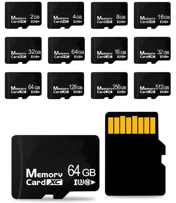
The three formats do not share one range, and the ceilings differ by more than people expect. The TF card runs 4GB to 256GB. The semi-finished board runs 128MB to 128GB. The UDP module runs 4GB to 32GB, because its package is the smallest of the three and the die has to fit inside the epoxy. Those are not marketing cut-offs — they are where each body stops closing.
Where each band stops making sense
| Band | Which of the three reach it | What it still fits | Where it stops working |
|---|---|---|---|
| 128MB–512MB | Board only | A bootloader plus a config partition. A device that carries an identity and a licence file and nothing else. | The workload adds logging, or a firmware update needs a second slot, or a language pack arrives. |
| 1GB–2GB | Board only | A logger writing a few MB a day. A device read constantly and written rarely. | Video appears. Or the firmware image grows until a duplicate slot no longer fits. |
| 4GB–32GB | All three | Most industrial, retail, education and automotive work. | The product records continuously and the customer expects weeks of history, not days. |
| 64GB–128GB | Board and card | Long-history logging, map bundles, kiosk content, media shipped on the card. | You are paying for a band the workload never touches, in a die grade that is harder to source. |
| 256GB | Card only | High-resolution capture, on-device 4K, large offline media. | The enclosure is sealed and hot, and nobody measured retention at that temperature. |
Read the table by its fourth column, not its third. Every band in the list still sells. The question is which one your workload leaves first — and, before that, which of the three formats can even quote it.
The number on the card does not move; the room behind it does
A nominal 32GB card reports about 29.8GiB to a binary host. It reports that at 0°C and at 70°C alike, because the decimal-to-binary gap is arithmetic, fixed by the SD specification, and thermal conditions do not touch it.
What temperature changes is how much of the die the controller still has to work with. Heat raises the raw error rate of the cells. The controller answers with read retries and block relocation, and every relocation draws from a spare-block pool that was finite on the day the part was built. As the pool drains, write amplification climbs — more physical writes for the same logical write, more heat, fewer spare blocks. It is a loop that feeds itself.
This is why the same 32GB part can be right for a 24GiB payload in a ventilated enclosure and wrong for that same payload in a sealed box bolted to a chassis. The label is identical. The available room is not.
Three margins between the label and the space you can use
| Margin | Rough size | What happens if you leave it out |
|---|---|---|
| Decimal to binary reporting | About 7%. A 32GB part reads as ~29.8GiB. | Your customer plugs it in, sees 29.8, and files a short-shipment claim. |
| Controller firmware and bad-block replacement | Small, and specific to the part. | The first grown bad block eats the file system instead of the reserve. |
| Over-provisioning reserve the workload spends over its life | Not published by anyone. | A part that passed at 25°C starts relocating at 70°C, and write speed falls off a cliff mid-project. |
The first margin is arithmetic. The second is a correction you can ask a supplier to state. The third is a firmware choice, made by whoever wrote the controller, and no datasheet in this industry quantifies it.
For the arithmetic side, the card’s own reporting rules are in SD Specifications, Part 1, and we keep a plain-language version of the same gap on the nominal vs usable capacity page.
Why heat spends the headroom faster than a bench does
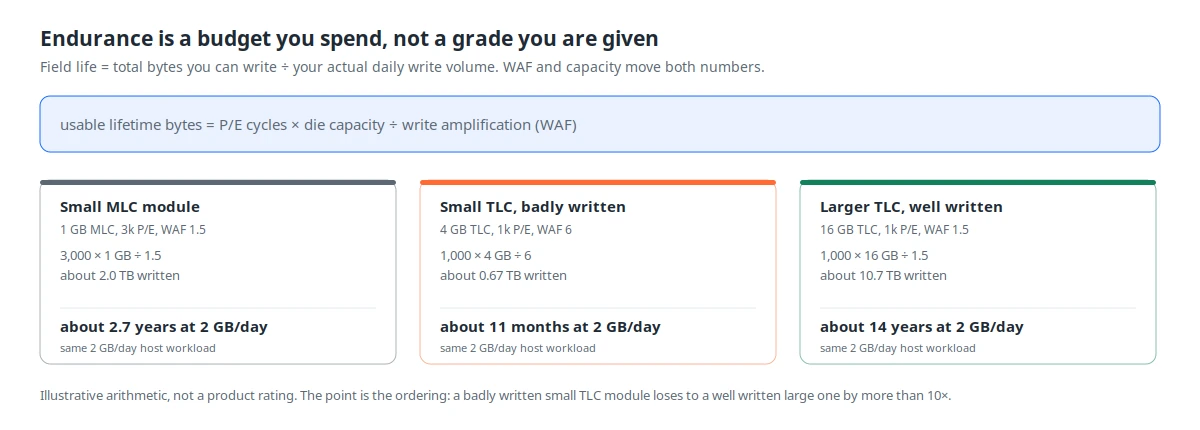
Endurance is a budget you spend, not a grade you are handed. Usable lifetime bytes equal program/erase cycles times die capacity divided by write amplification. All three terms move with the band you pick and the heat you put it in. A well-written 16GB TLC part and a badly written 4GB TLC part differ by more than ten times in field life at the same 2 GB per day — that is the ordering the diagram is making, and it is why “bigger capacity” and “longer life” are not the same sentence.
JEDEC’s published retention figures make the temperature point concrete: roughly ten years at 40°C at start of life, falling to about one year at 40°C after 3,000 program/erase cycles. Forty degrees is a cool number for a metal enclosure in a vehicle, a kiosk in a shopping centre in July, or a camera housing on a pole. Ask what the retention assumption is at your enclosure temperature, not at the standard one.
What a read-back test proves, and what it leaves out
Fill the whole advertised capacity, read every byte back, compare. H2testw on Windows, f3write and f3read elsewhere. That test proves integrity at the temperature you ran it, and it is worth having — it catches mislabelled and downgraded parts before they reach a line.
It proves nothing about the spare pool, because the part reports no internal figures to a host. A card can pass a full read-back at 25°C and still fail in the field at 70°C, and the certificate will not have warned anyone.
So put the temperature on the certificate. “Passed full-capacity read-back at 25°C” is a true statement. “Passed” alone is a statement that will be read as covering conditions nobody tested. Sampling follows ISO 2859-1, so the check applies to a defined lot at a defined AQL rather than to one unit pulled from a tray.
Six lines for the RFQ
- Usable capacity in GiB, plus the tolerance you will accept between units.
- The temperature the enclosure actually reaches, measured on a running unit — not the grade printed on the datasheet.
- Daily write volume and the service life you are promising, in GB per day and years.
- Whether the workload needs power-cut atomicity, because that changes the firmware requirement, not the capacity.
- The test temperature and the sampling plan, so the certificate is checkable later.
- Whether the die supplier and grade are fixed for the programme, or allowed to float between lots.
Six lines, and the capacity conversation stops being about the biggest number on the page. Most of the disputes we see are not capacity disputes at all — they are missing lines four and five.
If the format is still open, the semi-finished board and UDP module pages carry their own ranges and envelope limits. For the difference between consumer and industrial die at the same capacity, see consumer vs industrial. And when the number is set and you want it quoted, what to send for a quotation lists the rest.
Sources
Frequently asked questions
What capacity ranges do WINTEL's three flash formats cover?
The TF card runs 4GB to 256GB. The UDP (USB Disk in Package) module runs 4GB to 32GB and the semi-finished board runs 128MB to 128GB. Only the card reaches 256GB. Each format stops where its body stops closing, and the three ceilings are different numbers.
Is a larger capacity always the safer choice?
No. Over-specifying is silicon you pay for on every unit and never write to. The flash still ages and the controller still draws its standby budget, so the largest tier earns nothing back while it weakens your margin. The safe choice is the smallest tier your workload will not outgrow in twelve months — unless the part runs hot, in which case the reserve behind the reported capacity matters more than the number in front of it.
Why does a 128MB or 4GB part still exist in the catalogue?
Because some roles are tiny. A 128MB part holds a bootloader plus a small config partition; a 4GB TF card suits a logger that writes a few megabytes a day. They stop making sense the moment the workload includes continuous capture or a large firmware image plus a logging partition.
When does a UDP module make more sense than a TF card on capacity alone?
When your design is soldered and sealed and needs at most 32GB. The UDP module runs 4GB to 32GB and disappears into the PCB stack, while the card needs a socket. Above 32GB the semi-finished board or the card applies, so the envelope decides before the capacity does.
Does the memory brand change across capacity tiers?
Sourcing spans six suppliers — SanDisk, Toshiba, Micron, SK Hynix, Intel and Samsung — and grade and availability shift with the tier you ask for. Mid-band requests are easier to source stably than top-end ones, because the largest dies are the most exposed to allocation when the market tightens.
Can I mix capacities within one production run?
Yes, but each capacity is a separate die-and-controller configuration with its own sourcing and test path, so mixing tiers inside one run affects both lead time and batch traceability. Fix the capacity per programme and re-qualify only when the workload changes.
Does a card physically hold fewer bytes on a hot day?
No. Nothing in the reported capacity moves with temperature. A nominal 32GB card reports about 29.8GiB to a binary-reporting host at 0C and at 70C alike, because the decimal-to-binary gap is arithmetic rather than thermal. What changes is how much of the die the controller still has available to work with: heat raises the die error rate, the controller spends its finite spare-block pool on retries and relocation, and the headroom behind the reported number drains faster.
Why does a part in a sealed enclosure age faster than the same part on a bench?
Because the enclosure holds the heat in. NAND cells lose charge retention faster at elevated temperature, and the controller reacts by relocating blocks and consuming its spare pool. The published JEDEC retention figures are stated at 40C, which is a cool number for a metal box bolted to a chassis in a vehicle. Ask for the retention assumption at your own enclosure temperature, not at the standard one.
How much headroom should a specification carry above the payload?
Enough to cover three deductions, not one: the decimal-to-binary reporting gap, a slice for controller firmware and bad-block replacement, and the over-provisioning reserve the workload consumes over the service life. Nothing in the public standards quantifies the last slice, so it has to be measured on a pre-production sample before the number goes into a drawing.
What temperature range should a custom flash order specify?
The one the enclosure actually reaches, not the one the datasheet leads with. The commercial grade is usually quoted as 0C to 70C and the industrial grade as -40C to 85C, though those figures belong to the specific part rather than to a single standards body, so confirm against the latest official wording. A part rated 0C to 70C inside a sealed housing can spend its whole life above its own rating.
Can write-and-read-back prove capacity at temperature?
It proves integrity at the temperature you ran it, which is worth having — fill the whole advertised capacity, read every byte back and compare, with H2testw on Windows or f3write and f3read elsewhere. It does not prove anything about the spare pool, because the part reports no internal figures to a host. If the test ran at 25C and the product ships at 70C, the certificate should say 25C.